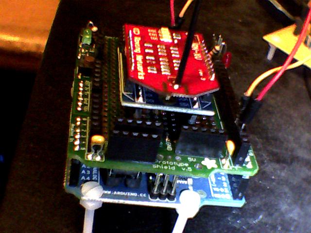
Roving Networks RN-XV, plugged into XBee adaptor/breakout,
plugged into 'proto shield', plugged into Arduino Uno
In an extremely affordable way, it is possible to create networked devices using a microcontroller, both WIRED and WIRELESSLY, in order to accomplish just about anything you can think of that is possible to do with a microcontroller (and maybe a few things that are otherwise IMPOSSIBLE). Aside from the obvious shields you can purchase for Arduino (ethernet, wireless) there are a couple of chip makers that produce the actual devices that makes this possible. Having done a bit of work and study on both of them, I thought it might be helpful to "the community at large" to write up a short review. Yes, other devices exist, but these are the ones I found to be MOST useful for me, as well as being cost-effective and reasonably easy to work with.
Keep in mind that BOTH of the devices I reviewed are capable of using SPI. One of these devices has serial I/O available as well, and the other has a parallel method of accessing memory. They both require a 3.3V regulated power supply that is capable of delivering at least 200ma, and in the case of the RN-XV, a level converter (I used a CD4050 non-inverting buffer for this, you can use whatever method you like, as long as you don't apply more than 3.3v to any input pin). But if you do not want to design and build your own board, Arduino shields are probably going to speed you along for your project prototypes. And companies like Digikey, Sparkfun, Mouser, Adafruit and many others typically offer one or more network communication devices that are capable of doing what you need.
Although the devices mentioned here are CAPABLE of achieving network speeds of 100Mbit (for ethernet) and 54Mbit (802.11g modulation), actual throughput of 1 to 2 Mbits is more realistic. This is more of a limitation created by the serial and SPI interfaces, and the microcontrollers that typically run at clock speeds around 16Mhz. So you can't expect high speed data transfer rates for your microcontrollers, at least not yet. What you CAN expect is that they (generally) won't interfere with the performance of the rest of your network, and you'll be able to directly communicate to your microntroller devices using a LAN or Wireless AP.
The first of these network device that I have tested is the Wiznet W5100, which is available for the Arduino as the Ethernet Shield and is also commonly available as a 'breakout board' from various sources. This device typically communicates via SPI (the way it is wired up on the Arduino shield), but also has a parallel interface consisting of 15 address lines and 8 data lines (which I did not test). If you have direct I/O bus access available to peripherals, it might make a lot more sense to use the parallel method to get better performance. But with a microcontroller, managing 23 GPIO lines for addressing and processing network communications makes little sense, and would probably be SLOWER than using SPI. So for the sake of this review, SPI is the only communication method being used.
The Wiznet W5100 operates at a 'mid-level' but still requires a software device driver of some kind to manage communications and correctly handle packet data. A lot of the necessary handling of packets and protocols is provided for you (like MAC resolution, IP filtering, IGMP, UDP headers, TCP protocol-specific behavior, and so forth) but data for UDP is STILL managed at the packet level. TCP data is generally treated as a stream and will buffer up to the available memory for a 'socket'. In fact, communication generally behaves very similar to a regular IP 'socket' as defined by a 'Berkely Sockets' implementation (which includes windows), and up to 4 'sockets' can be open simultaneously (if your driver supports it properly). Both listening and outgoing TCP connections can be made, as well as receiving and sending UDP packets. However, only socket 0 can perform 'raw socket' or 'PPPoE' operations.
The Arduino software library includes the Ethernet Library which provides a 'wrapper class' for working with TCP and UDP connections. The most recent library also includes support for DHCP, though a few other (3rd party) versions also exist, and offer additional capabilities (such as DNS support). The Arduino network library and sample code can be a good starting point for developing a microcontroller application that can communicate over the network using the Wiznet W5100.
Electrically, the wiznet device requires a 3.3V regulated power supply that can supply up to about 200ma. If you read the spec sheet (page 63, 'Electrical Specifications') you'll notice that current draw might actually exceed 180ma at certain times (it's listed as a maximum value). Fortunately you won't need level conversion with this device as the inputs and outputs (for SPI at least) are 5V logic tolerant. This makes wiring it up to a 5V microcontroller (like Arduino) a LOT easier. If you do not use an 'integrated transformer' ethernet connector (commonly found on breakout boards), you will need to provide proper transformer protection between the ethernet connector and the W5100. The breakout boards and Arduino shields that I have seen have done this FOR you already, and even supply traffic indicator LEDs. But if you are wiring it up yourself for your own board design, you should read the spec sheets carefully and purchase compatible hardware to go with it.
Greatly simplifying the use of 802.11g WiFi, the Roving Networks RN-XV that is based on their RN-171 wifi module, comes with an 'XBee' pin-compatible set of headers (warning: 2mm spacing!) that fits DIRECTLY into any XBee-compatible socket, including the Arduino Wireless Sheild, as well as any number of XBee breakout adaptors such as THIS one from Digikey. In my case I built my own Arduino shield using an XBee breakout adaptor, which was actually not all that difficult, especially when using a Proto Shield kit from Adafruit. My purpose was MOSTLY to understand the electrical requirements for mounting this on a board of my own design, and so building the prototype shield for it helped me figure it out better.
The RN-171 module is essentially a 'serial communication' device with an intelligent Wifi component, operating with a high level interface. It uses a 'command mode' to perform management actions, such as scanning for networks, setting up the WIFI connections, configuring serial parameters like baud rate and whether or not 'terminal echo' is enabled, status messages that are sent on connect/disconnect, and so forth. Additionally the device has a number of I/O pins and sensors that can be individually programmed, to the point where periodic UDP packets will be sent to broadcast or a specific IP address (your choice) with the I/O values for the various measurements. By all rights, a properly configured RN-171 could work even WITHOUT a microcontroller and periodically report its measurements. Its value for microcontrollers, however, is that it can SUBSTITUTE for a USB or serial port interface, making remote device communications relatively easy. A microcontroller such as an Arduino will typicaly have a series resistor in the Tx/Rx circuit that would allow you to 'swap in' a different device to send/receive serial data from. In fact, the Arduino Wireless Shield has a switch that allows you to determine whether the wireless device is in the TX or RX path (basically it swaps the TX/RX lines around on pins 0 and 1). So with the switch in one position, the serial device would 'talk' to the wireless device (for this to work the microcontroller would need to be removed or disable its serial port), and in the other position, to the microcontroller.
Programming the RN-171 module is relatively easy, but you'll probably spend a bit of time reading the documentation before attempting it. In short, you can save your configuration as the 'default' and programatically load different 'saved' conditions as needed. The configurations are actually saved into a type of flash file system, and can be referred to by name. Additionally, firmware downloads can be performed and saved into this same flash file system, which actually enables you to boot multiple firmware versions. There is also a mechanism for factory reset, Wifi Protected Setup (not recommended by ME due to recently discovered security issues within the protocol itself), programmable use of a GPIO pin to perform 'connect' actions or inform you of a connection, sleep with automatic 'wake up' on a timed interval, and a whole lot of other useful features that I don't have room to describe. It's enough to say that it has a LOT of features that I have not had the time to evaluate.
With the latest firmware (version 4.00, April 2013) the RN-171 module ALSO has a 'Soft AP' mode. It only appears to support unencrypted connections, however. Still, you should be able to connect up to 7 clients to it (limited by the DHCP server) simultaneously, and the clients can route IP traffic to one another as they would be able to do with a regular access point. What this means for you is that YOUR DEVICE does not need to associate with an access point for a remote client to connect with you. YOU can BE the Access Point! And the flexibility that this gives you is VERY nice, indeed.
On the down side, it appears that you can ONLY manage a single TCP connection at a time, since all of the communication appears to take place via the serial port or SPI interface (I did not test the SPI interface as it did not have its pins broken out on the RN-XV; however, I could STILL solder wires onto the RN-171 module itself if I wanted to have this capability, since the module pins are still exposed). That being said, it's not likely you would NEED more than one connection if all you are doing is broadcasting UDP or periodically connecting to a web server or listening for connections to your device (and responding to them accordingly). For a microcontroller, a single TCP connection is probably the ONLY option, and using the serial port is convenient. Additionally, with a lack of SPI, communication rates are somewhat limited. According to the documentation, serial baud rates up to 1Mbit are supported, though it recommends enabling (and using) hardware flow control via the RTS and CTS lines. Additionally, the documentation suggests limiting data lengths to that of a single packet to avoid overrun, whenever bit rates exceed about 600kbaud. Still, with SPI the documentation states that speeds up to 2Mbits are possible. This IS still significantly LESS than the speed of the 802.11g protocol, but just how much speed do you really NEED for a microcontroller anyway (especially microcontrollers that run at 16Mhz and only have 4k of RAM!).
And this DOES surface another minor 'nit' that could cause trouble for people unfamiliar with 802.11, in that you must PROGRAM IN the modulation rate ahead of time, and it does not appear that any kind of 'automatic rate management' is available. But you COULD monitor RSSI levels yourself with SOME programming effort, and make up your OWN rate management algorithm based on that. Good luck with that, if you do. Otherwise, the DEFAULT modulation rate of 24Mbit is probably adequate. NOTE: I do _NOT_ recommend using 'b' modulation rates, EVER. They tend to interfere with your wifi network, for various reasons.
Electrical requirements for this device are a bit more restrictive than those of the Wiznet. In addition to the 3.3v regulated power supply, you MUST use a 5V logic level converter of some type for any signals being sent INTO the device from 5V logic outputs (such as those from an Arduino microcontroller). I found that one of the simplest ways to accomplish this was to FIRST allow the 3.3v output pins to drive the input pins of the microcontroller directly, and SECOND, to drive a CD4050 from the same 3.3v power supply as the RN-XV (or RN-171) and then direct all 5V logic signals through the CD4050 and into the RN-XV. The CD4050 is VERY tolerant of input signals that exceed its Vss value (in this case 3.3v) and will then buffer the logic levels between Vss and Vdd (compatible with the RN-XV). A single CD4050 has 6 gates, more than enough for serial + flow control and/or SPI, and perhaps driving GPIO pins for reset or various other triggers. And there is one additional precaution: if you wire up an RN-171 device yourself, you will need to make sure it has a proper antenna BEFORE powering it up. Otherwise, operating a radio device like this WITHOUT an antenna can easily destroy it. Fortunately the RN-XV comes with a 'wire' antenna that I had to 'bend straight' (it was bent over in the package) but is made of a type of wire that doesn't have trouble bending. So no need to solder on a u.fl connector, coax, or anything else that might prove difficult.
It is worth pointing out that both of the devices that I reviewed here LACK IPv6 SUPPORT. Understandably IPv6 is not that widespread in its use. Further, unless you need IPv6 on your device, IPv4 would be adequate [you could always build an IPv4 to IPv6 gateway of some kind via port forwarding, etc.]. Additionally, it means that you don't have to worry about the one downside of IPv6, that EVERY ADDRESS IS PUBLIC, meaning that someone cracking your device from the outside world is highly unlikely (unless you assign a public IPv4 address). And because including an IPv6 stack just adds extra silicon space to the design, it's likely that IPv6-capable devices will be more expensive. In the long run, IPv4 will be around for quite a while, and for private-only networks, it's just fine.
I've had some extensive experience working with this particular module, including a nice breakout board available from Sparkfun. Note it is the "non-HID" version I refer to here; the HID version uses special firmware to emulate a "Human Interface Device".
One of the BEST features of the RN-42 is its simplicity. Simply connect the serial lines to the appropriate RX and TX lines on your microcontroller, and VOILA - you have bluetooth! The 'default' serial configuration uses the bluetooth in 'slave' mode and allows you to connect via serial emulation. The default serial baud rate is 115k(N,8,1) and it can be reset using a 'factory reset' capability [note this pin may not be exposed on the Sparkfun module]. And if you have hardware flow control capability [I wrote code to do this for the xmega] you can run as high as 460kbaud. And that's not bad.
Since it uses the RFCOMM serial protocol, you should be able to connect to the RN-42 (or from an RN-42 if you switch modes) using a simple bluetooth adaptor and a Raspberry Pi. I have actually done this.
NOTE: On the Raspberry Pi (using Raspbian) you will need to install the 'bluez' and 'bluez-tools' packages in order for bluetooth to work.
The two (raspberry pi 'raspbian') scripts I used are:
The downside of the RN-42 is that it requires a serial port, and ATMega devices only have ONE, and it's used for flashing as well
as for regular communications. Using the 'avrdude' application it is possible to flash an Arduino-compatible device via the default
serial port as long as the baud rate is set correctly on the bluetooth device, AND there are no communications/noise issues. I have
successfully flashed at 115k baud with an xmega, but some of the ATMega 'compatibles' work better at 56k baud. The Arduino bootloader
is set up for 115k baud, but I have not actually tested it on an Arduino. Still, as long as your bootloader can factory reset the
bluetooth and/or set the baud rate correctly beforehand, you should be 'good to go' to flash via bluetooth.
So, in other words, if you hard-wire a bluetooth to the default serial port on an Arduino or compatible, you should still be able to
flash the device, if you are careful about how you set it up (both hardware and firmware).