SFT Component Tester Project
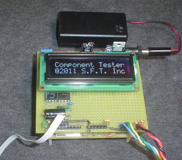
The SFT Component Tester is a microcontroller-driven test signal and measurement unit that uses
various common "ohm meter" style test methods to determine whether or not a component
is good or bad, and the type of component being tested. The primary purpose of the design was
to test a number of 'Proof of Concepts' for microcontrollers in general, as well as discovering
the limitations, known design issues, and as many "unknown" or "unexpected"
issues that a single project might be able to uncover.
This device is certainly a "work in progress". It was my original hope that I could build
an in-circuit test device that would allow me to identify bad parts without actually removing them
from a circuit, by testing the device with "safe" signals. Although the hope of that feature
remains, I am still working on the basic functionality of the device.
This project remained 'on the shelf' for quite a while, in favor of other projects, because of a problem
I discovered with the A:D converter on the AVR microcontroller: Even though the DC input impedence of the
A:D converter is relatively high, the nature of the conversion causes 'inaccuracies' to appear when a series
resistance greater than about 10KΩ exists between a measured voltage and the A:D converter. This meant
that resistance measurements greater than 100KΩ would be highly inaccurate. All of my attempts to
reconcile this were pretty much futile. It meant a re-design to include op amp 'buffers' as well as a split
power supply to allow for the input voltage range being anywhere between 0V and 5V.
Features
- Simple interface - 3 colored test leads and one pushbutton with LCD display
- Reasonably fast operation
- Operates on 9V battery or external 9V (regulated) power supply
- Tests semiconductors, resistors, inductors, and capacitors.
- Detects semiconductor devices and determines whether good or bad (still need work on MOSFET, JFET)
- Designed to accurately measure resistance from 1Ω to above 10MΩ
- Design minimum measureable inductance approximately 100µH [TBD]
- Design minimum measureable capacitance approximately 10pF
- Design maximum measureable capacitance above 100,000µF
- (reserved, to be implemented) Electrolytic capacitor ESR calculation, based on charge rate and measured impedence
For a large value capacitor, the charge rate is used to determine its capacitance. However, electrolytic
capacitors typically have a large 'Effective Series Resistance' that can affect their impedence and
ability to filter power supply ripple. By calculating an estimate of the ESR, you can often determine
whether a capacitor is wearing out and needs replacement, even if its capacitance is still 'good'
- Calibration procedure via external software and serial port
- POSIX-compliant command line utility
- Also builds and runs on Microsoft Windows
- Procedure involves taking measurements on a single known resistor (10.0KΩ) and a 10% tolerance 0.1µF capacitor,
plus shorting specific test leads and taking 'open lead' measurements (when prompted).
- Calibration data is stored to NVRAM on the AVR microcontroller
Project Status
- Latest prototype, in progress 7/2013
- Placed CPU and regulator directly on the controller board, making for a more compact design. Official board design to follow.
- Added LF353 op amps to isolate A:D converters, and a simple charge pump to provide appx -4.5V to the op amps (supply is +9V/-4.5V)
- AVR's A:D converters were unequally loading high impedence devices, causing inconsistent measurements
- Research on the AVR microcontroller's A:D suggests that a high-Z buffer amplifier is necessary for any measurement above 10KΩ
- Charge pump is driven by the same 500Hz PWM output that provides an AC signal for testing reactive components, using the 9VDC power leg
- The re-designed controller board fits both a 2-line and 4-line LCD without difficulty.
- Additional software work needed to improve accuracy and accomodate latest design changes
Additional Photos
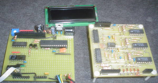
This is an exploded view of the assembled unit shown at the top of the page
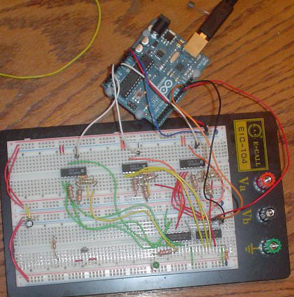
This is the original breadboard layout that tested the basic features of the device
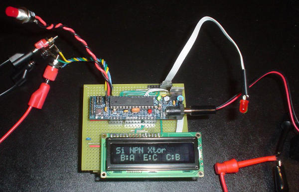
This is the first prototype, Nov 9, 2011. The main board underneath is not visible.
©2013 by Stewart~Frazier Tools, Inc. - all rights reserved
Last Update: 7/24/2013
Back to S.F.T. Inc. main page