A Simple Bed of Nails
For ISP/PDI Programming
|
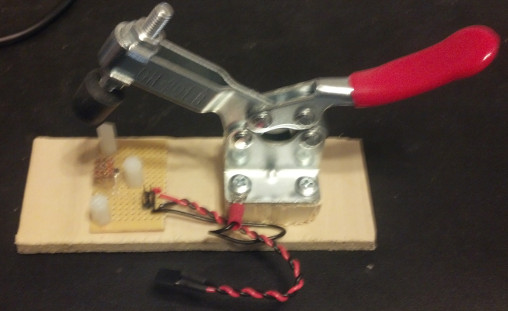
In many cases, you might be working on projects where you want to be able to program a microcontroller CPU with an initial firmware load, but not solder any pins onto the board to do it. This is especially important if you need non-default 'fuse' settings or need to put your own bootloader onto the device. For the ATMel® processors, in particular the ATMega and ATXMega processors, you would use an ISP or PDI header (both look the same and often use the same programmer for either one) to program initial firmware (typically a bootloader that lets you flash it via serial port or USB), and set the 'fuses' that determine what the clock type is, what NVRAM areas are programmable, what areas are not, etc.. The ISP/PDI header is a 3x2 pin layout with 0.1" spacing, similar to a typical breadboard. You'll often see one or more of these 3x2 pin layouts for ISP/PDI on an Arduino or 'clone' board, sometimes with pins, sometimes without. Other processors would have their own interfaces and pin connector layouts for similar purposes. 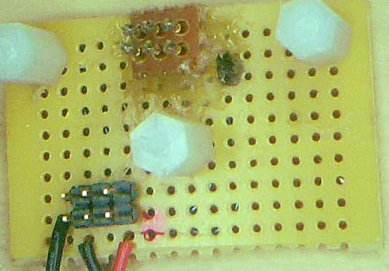 The above photo shows a closeup of the 6 pogo pins (top, center), the nylon standoffs, and the ISP/PDI header with a power and ground connector (lower left). The ground connector is wired up to the metal clamp, to help protect against static discharge. The power connector is intended to provide external power to the board while you are programming it (this is optional, but in my case I need it for some things, but not for others). A typical ISP/PDI programmer would then plug into the 3x2 connector (note red dot for polarity), and you would use the clamp (top photo) to press the board down onto the pins. Of course, you may want more than JUST a ISP/PDI connector. You might want some test points. But for this kind of setup, you would need to build a custom rig for each board. For demonstrating the concept, I built a 'universal' bed of nails that only programs via the ISP/PDI pins. So, no more soldering the 3x2 header on every board any more. That should save a bit of time and effort! In the manufacturing world, a 'bed of nails' will typically be part of the final assembly and test process. Once a board has been built, you'll typically have a bunch of test points on it, and they'll fit over a 'bed of nails' rig. That rig would need to EXACTLY fit the board, and it would probably have one or more clamps on it to press the board down (without breaking anything) and compress the pins enough so that they all have good electrical contact. Then "something" (let's say an RPi or an Arduino, or a commercial testing device) would then apply voltages, test signal levels, and so forth, and determine whether the unit is good or bad. And so this universal 'bed of nails' is particularly good for flashing bootloaders and setting the fuses on a typical microcontroller, but it probably won't work well for anything else. Still, it's a time saver. So it would be worth building one of these for your own microcontroller arsenal. |
Key components used in this mini-project (from Adafruit)
|