Description
The 'SFT Synth' (code named 'Piranha') is a monophonic single-voice MIDI programmable synthesizer
built with a minimal number of components and controlled using an Atmel AVR processor. Versions 1
and 2 used an ATMega328p. Version 3 uses an ATXMega32e5. It is programmable using a computer with
a 3.3v TTL serial adaptor, running the 'SFT Synth Programmer' application. The application is designed
to run on Windows 7 or later (32-bit or 64-bit OS) as well as on POSIX systems running X11 (such as Linux
and FreeBSD), and [potentially] native OSX, using wxWidgets.
An Android application, targeting 4-inch 'slab' devices, is being considered.
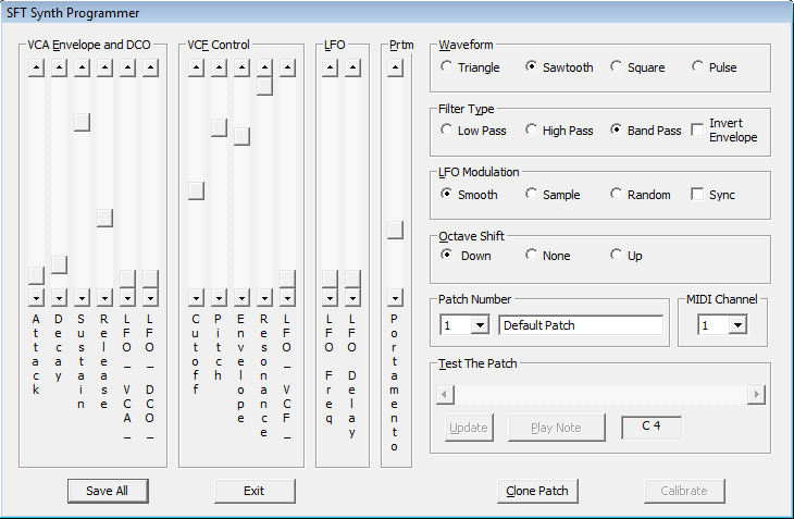
A screen capture of an early version of the SFT Synth Programmer application on Windows
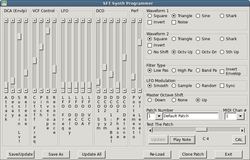
A similar screen capture of a newer (wxWidgets) version of the SFT Synth Programmer application that supports V3
Why is this an 'Amazing Thing'?
I like to cite this project as a major accomplishment for a number of reasons...
First of all, I'm using an AVR microcontroller (albeit an xmega) with only 4K or RAM and 64k of NVRAM (minus the bootloader) to perform all
of the control functions, including MIDI and patch programming, as well as the (dual DCO) tone generator, envelope timing, and modulation.
And with dual serial ports, one for MIDI, one for programming. Yeah.
Second, I've come up with a working design that would cost less than $100 to build (in very small quantities), assuming the circuit board
was produced at a reasonable cost. This makes it a viable retail product to be sold at a retail price of between $200 and $300,
which is comparable to existing synthesizer products. And because it's designed to have little or no calibration, it could sell for even
LESS than competing products, and be manufactured in an automated shop.
Third, it uses an ISR to drive the tone generator, using the maximum possible interrupt frequency (around 70khz), which [for several reasons]
approaches the limits of the CPU's ability to process the ISR effectively. To compensate for pushing limits like this, I _also_ allow
portions of the ISR to be 're-entrant'. This has a minimal effect on the tone, but ALSO helps minimize 'FM' distortion of the tone's
frequency [which is pretty irritating when you hear it].
Fourth, it's a prime example of Emulating Hardware through Software.
And, with control software running 'cross platform', and the likelihood of making it all 'open source', it has a potential appeal
to the kinds of experimenters that might want to customize the firmware for unique sound possibilities.
Update as of July, 2018
A major improvement to the V2 design from over 3 years ago, the V3's DCO features dual tone
generators and greatly improves the sound quality. Additionally, the VCF is far more accurate
with extended range as compared to the earlier version. This is primarily due to the increased
speed and advanced peripherals found in the ATXmega32e5 processor, as well as improvements in
the overall design.
Additionally, programming for Version 3 uses a second serial interface at 115kbaud. Plans are to use
an FTDI or similar USB to serial bridge. For now, it uses an 'FTDI friend' or similar cable.
A proof of concept version, using a 'proto board', significantly reduces the total parts count,
while simultaneously improving the quality WAY beyond original expectations. Version 3 will cost
less to make, be physically smaller, and likely support an on-board USB serial device (like FTDI)
rather than requiring an external serial device to be plugged into it. The proof of concept design
is working as expected and I will add information to this web page as the project moves forward.
Some of the information on this page pertains to Version 2 and earlier (including the sound
clips). When I have some good sound clips available for V3, I shall make them available from this
web page. In general, V3 is less 'buzzy' and has additional waveform capabilities that you'd expect
to find on high end synthesizers, suchy as dual DCOs with de-tuning capability, true sine wave
generation, symmetry control, 4 noise colors, and so on.
The 'SFT Synth' uses a standard MIDI interface to receive MIDI controller and program commands.
The newest prototype includes a 'MIDI through' connector so that the devices can be 'chained'.
Previously this was a 'MIDI out' but its usefulness was questionable at best, and the ability to
chain a series of devices together is FAR more important.
Additionally, there is both an external serial (3.3V TTL) and a place for a PDI header on the board,
for somewhat easy re-programming of the AVR microcontroller (necessary for possible open source licensing
of the bootloader). The pin arrangement for the serial port is compatible with popular USB/Serial devices,
such as the 'FTDI friend' available from Adafruit.
NOTE: the PDI header in this design does not have enough room around it to accept a normal 6 pin plug;
however, a 'bed of nails' programmer should work, provided that the clamp's plunger is small enough to fit.
Features
- Monophonic MIDI synthesizer, controlled by AVR microcontroller with minimal additional components
- Firmware-based AVR microcontroller solution using the Atmel ATXMega32e5
The firmware is intended to be open source, built with the Arduino IDE and the
XMegaForArduino Project board support files; as such, it could
be customized in a way that makes the hardware it runs on even more valuable to end-users, especially for
producing unique sounds and effects.
- Can be powered by either a 9V battery or an external 9V power supply (firmware programming with 9V battery not recommended)
NOTE: The external 9V supply should be an old-style 'wall wart' type of power supply, and therefore not produce a 'ground loop'
audible noise problem, which is (unfortunately) very common with switching power supplies.
- Standard MIDI (IN,THROUGH) interface, with a separate TTL serial port for programming
NOTE: an FTDI chip (or similar) USB serial bridge may be added to the design, for USB serial programming.
- Patches programmed by an external computer running the SFT Synth Programmer software via a 3.3v logic compatible USB serial device.
The programming software is compatible with Windows 7 or later, as well as Linux and FreeBSD (via wxWidgets).
An Android version is being considered, which would be designed for use with an inexpensive 4 inch 'slab'.
An iPad version is not being considered at this time.
- Dual DCOs feature advanced capabilities, including true sine wave generation, for C'-1' through C7. Phase and symmetry controls,
as well as DCO balance, allows for a significant level of control over the tonal qualities of the sound.
- Noise generation includes Brown (red), Pink, White, and Blue noise, based on the frequency of the played note.
- Currently stores 16 patches within the AVR device's EEPROM, selectable via a MIDI 'patch select'.
NOTE: The SFT Synth Programmer software is required in order to customize patches. Patches can be saved to and loaded
from specifically formatted text files. Each patch is named as well as being numbered 1 through 16.
- VCF
- Self-aligned using the programming software.
- Uses a 'Steiner' active filter with ROHS compliant components. Selectable as Low Pass, High Pass, or Band Pass,
with frequency range extending from ~C0 to ~C8
- Adjustable 'Q' (filter resonance) for all 3 filter types
- Selecting Low Pass with maximum frequency effectively bypasses filtering ('all pass').
- Non-patent-encumbered filter technology (from 1974), with minimal drift and no cadmium-containing components
- DCO
- Generates square, triangle, sine, and 'sharkfin' wave shapes, accurate to ~0.1%, with variable symmetry and phase relationship between
two DCOs.
- The DCOs may also be de-tuned between 1/64 and 1/4 of a half-step in pitch, with optional up/down octave shift and '5th up'.
- "Colored noise" capability (brown, pink, white, blue)
- Entirely implemented in software, eliminating many external components and any need for alignment.
- Programmable Voice Parameters
- DCO: LFO effect level, Portamento time
- LFO alters the DCO frequency up to '1/2 step' for vibrato effect
- Portamento evenly 'sweeps' across semitones over an adjustable delay time, between the previously played pitch and the currently selected one
- DCO detune, DCO balance, DCO 1 and 2 polarity and symmetry, DCO 2 phase shift, as well as overall 'patch volume' sound level.
- VCA: Attack time, Decay time, Sustain level, Release time, LFO effect level
- VCF: Cutoff frequency, Pitch effect level, Envelope effect level, Resonance, LFO effect level
- 'Cutoff' applies equally to all notes and is the 'base' value for the VCF effect
- 'Pitch' adjusts how much effect that note pitch will have on the VCF
- 'Envelope' adjust how much effect the envelope signal will have on the VCF
- 'Resonance' adjusts filter 'Q', adjustable from 0 to 7. The maximum resonance for each filter has been designed to operate just
below the point of oscillation, with a more prominent effect for the bandpass filter.
- LFO: Frequency, Delay time, Signal Type (Smooth, Sample, or Random)
- The LFO is emulated as a free-running cosine wave for more natural sounding effects
- 'Smooth' applies the LFO signal directly
- 'Sample' applies the LFO value captured at 'note start'
- 'Random' uses a pseudo-random value captured at the start of the LFO cycle
NOTE: 'random' is actually more of a 'mix-up' as "truly random" tends to sound bad. The 'random'
sequence was specifically chosen to sound good, especially when applied to the VCF.
- Responds smoothly to MIDI 'Note Bend', full scale fixed at 2 "half steps", in either direction.
- Uses standard components, specifically chosen to be readily available, reasonably priced AND ROHS compliant
Reserved Features
- One or more banks of 'pre-set' patches that can be downloaded from the device, modified, and then individually assigned to
one of the custom patches, using the programming software
- Simple (semi-automatic) alignment procedure for VCF using the control software, using a simple 'walkthrough' procedure.
This makes it possible to release in 'kit' form, as well as simplifying the final assembly+test procedure.
- LFO may be optionally synchronized to MIDI timing events (useful for synchronizing the LFO with note timing).
- Identifies itself on MIDI Out via MIDI SysEx message [pending registered MIDI device identifier assignment]
Project Status
- (8/4/2018) V3 prototype circuit board built and tested (see photo), with minor tweeks to the firmware for better overall behavior.
The new design uncovered a couple of issues that have probably been there all along, and so the resulting sound quality is now a
bit better than it was before. I also noted that, with certain symmetry settings, certain audible tone artifacts are actually
consistent and controllable in a way that enhances the device's capabilities, giving certain symmetry settings (especially 'shark')
a 'bell-like' quality at higher note frequencies. This is primarily caused by assymetric waveforms generating partial
sinusoidal signals and/or harmonics (especially 'shark') at frequencies related to the shorter side of the cycle. This is a known
side-effect of assymetric waveforms, and why the symmetry adjust exists in the first place.
- (7/23/2018) V3 board design nearly complete, needs final review. Prototype firmware issues nearly resolved. Noted some tone
artefacts above C7, some of which can be ignored since the DCO officially doesn't support notes above C7. Tone artefacts between
A5 and C7 are, for the most part, at acceptably low levels. These are primarily due to the limitations of CPU speed and ISR
frequency. Increasing both would eliminate the artefacts, if it were possible to do so. Otherwise, tones could be generated
all of the way past C8 to the 'max MIDI note' above C9.
- (7/11/2018) Project resurrected due to new design with ATXMega32e5 CPU, which eliminates about 1/3 of the components and potentially
makes the project easier for an end-user to construct from a kit. Initial layout is 2.25 inches by 3.25 inches on a dual layer
board, but is likely to get even smaller before it has been finalized.
- (9/3/2014) The newest 'V2' board design incorporates 5 SPI digital potentiometers to test the basic concept, as well as additional
noise filtering and a better layout to reduce background noise [which works perfectly]. Some corrections were made to the design as
'blue wires of salvation' which are visible in the photo. This design uses one SPI pot to control the VCA, one to control VCF resonance,
and 3 more to control the VCF alignment parameters. Additional tweeks to component values should improve the accuracy of the
alignment procedure and overall performance.
Summary of Improvements:
- Background noise is significantly lower
- Output level has been significantly increased (previously higher levels had excess distortion; design changes eliminate this problem)
- Overall performance of the VCA and VCF have been significantly improved.
- Digital pots enable software alignment of VCF, reduce BOM cost.
- Two 'original board' prototypes were built using the initial board design, 4" x 2" with 1/4" Phone jack output and MIDI In/Out
The first of these two prototypes was used for working out the 'kinks' and trying out various design changes.
The second prototype, using the same board as the first [but modified in a few places] incorporated various design changes,
including an SPI potentiometer for the VCA [which works better] as well as additional filtering and other design tweeks
(and corrections to the basic board design).
- Initial prototype built using 0.1" pre-drilled proto-board with single-side copper pads
- B.O.M. cost determined (source: Digikey), retail component cost appx 1/6 estimated retail price (excluding board, case)
LPR cost per unit is likely to be SIGNIFICANTLY below the expected retail price
Without the 20-turn potentiometers, it is even LESS (the digital potentiometers are less than $1 each)
- Created standard (preloaded) sound samples, 2 of which were used to create the 'Demo' song (using the original prototype)
- Initial marketing analysis performed, competing products sell for about TWICE the expected retail price
Additional Project Needs that MAY Require Outside Financing (including possible 'crowd fund')
- Enclosure design - 3D print of prototype design, tooling/mold for LPR. The case would also need a 'well' for a 9V battery
along with some kind of power switch, possibly on the volume control.
NOTE: battery operation would require some other minor circuit changes to support a power switch, as well as having
a battery connected while on external power.
- FCC Verification for Part 15 subpart B (unintentional radiators, peripheral device)
This may require a 'limited production run' in order to obtain a representative sample
- (optional) Additional testing for CE mark, others (this usually involves chemical testing on a destroyed device)
- Verify compliance with MIDI specification (possible third party), and obtain registered Manufacturer/Device ID from MMA [midi.org]
- Finalizing the board design (based on FCC/CE testing, manufacturability, other requirements) and LPRs to test
- Possible additional features [for marketing feasability]
- Legal research, trademarks, patent applications
Also, any applicable (existing) patent licensing requirements (unlikely)
- Production facilities for small-scale and large-scale assembly (outsource)
- Qualified technicians (or outsource) to perform final assembly and testing
This would include an appropriate 'bed of nails' tester for automated flash+test - I've done this before
- Marketing Channels
- Advertising
Demo Song and Sound Samples
- 'Rumble Synth' [*new* V3 remix] as OGG and
MP3 - Demo music featuring the V3 design, pounding synth bass
and portamento synth lead [a slight stereo chorus effect was added to the synth lead in the final mix], with backup from
General MIDI and a Roland JX-3P
This song is also available for streaming and
download at my
SoundClick band page.
- (V3) V3 Synth Demo - a VERY simple 'stand-alone' demo of 16 selected patches using
the V3 "perf board" prototype version of the synth. There are a few minor glitches in the audio (one appears to be a ground loop
problem, an audible background noise, switching power supply probably - I'll do a better demo soon) but it gives you a general idea of the
capabilities of the new design. Most of the patches use 'detune' on the 2nd oscillator to add a chorus-like sound. And the final patch
demonstrates 'pink noise', which sounds a bit like ocean waves when done properly.
NOTE: These patches (or ones that are very similar) may end up being presets in the final version of the firmware. The EEPROM size in the
CPU limits the total number of storable/programmable patches to 16, but there's no reason I can't include some presets as well.
Additional Photos
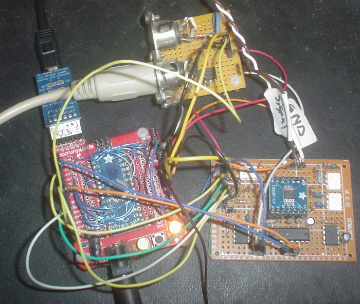
The third design (V3) (4th prototype), in 'proto board' proof of concept form. There are WAY fewer components!
And, with THIS design, there is almost NO need for calibration! (I may still include it for fine-tweeking)

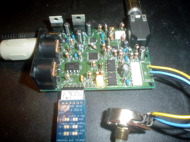
The second board design (V2) (3rd prototype), with a 'blue wire of salvation' clearly visible.
This design features digitally controlled potentiometers for several things, including the 'VCA' (now a DCA).
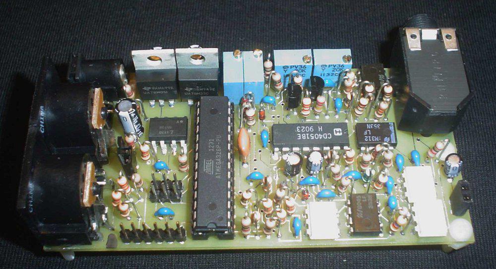
The 2nd prototype, basically a board design derived from the original prototype [with some improvements]
It has no ground planes, nor solder mask, nor silk screen [very very simple]
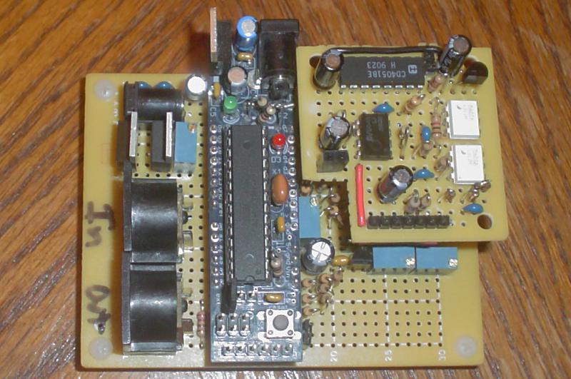
A photo of the original prototype, constructed on multiple 'proto boards' with an 'Arduino™ clone' board
(available from Adafruit) controlling it.
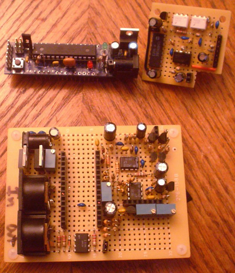
Another photo of the original prototype [exploded]. Many aspects of this design were abandoned.
|