PROJECT STATUS (as of 8/21/2018)
- 8/21/2018 - Web Site Update, include info on multiple CPU models, standardize around the
XMegaForArduino Project
- 5/2018 - Prototype for Arduino clone using ATXMega128A4U. Continuing previous work on USB, 2-wire.
The 128A4U has USB support and comes in a TQFP-44 package. This makes it work very well for experimentation, and developing
a proper 'Arduino clone' board layout.
- 2/1/2017 - added IDE support for new Arduino IDE HERE.
And here is the Package Manager URL.
- 10/27/2014 - A slideshow presentation describes various aspects of the project, including how to modify the Arduino IDE
- 10/4/2014 - added github project for support and continuing development for other XMega CPU's
- 6/15/2014 - Fixed compatibility issues with PWM on port E, added 'Tone' support for certain pins
NOTE: source updates will be made here. I'll also add a WIKI and other useful stuff
- Added support for hardware flow control on both serial ports. You're welcome.
Requires a properly modified 'pins_arduino.h'. See 'pins_arduino.h' for more details.
Basically, you set up a new board variant that has pre-assigned hardware flow control pins
- Initial publication (beta) - 3/13/2014
General Project Features
- Public project as of October 2014 (as mentioned before on github)
- Generally feature complete. Additional libraries and other support (USB, TWI, Tone) still needed, in some cases for specific CPUs only
- Simple, patch-based extension design - no need to maintain a separate development environment project for the xmega
Uses 'boards.txt' which allows you to create your own pin and CPU definitions for your own projects
- AVR compiler/library patches for ATXmega64D4, ATXmega32E5, and ATXmega16E5, and a patch for xmega startup code bug on the older FreeBSD compiler (debian and ubuntu have already been patched, as has the newest FreeBSD compiler)
- GPLv2 boot loader for ATxmega64D4 that supports serial port flash via avrdude, a similar protocol to the Arduino Uno
(for the 64D4, the existing 'stk500v2' protocol that is used by the Arduino still works since the image size is 64k)
This code may be freely used and/or modified for other processors according to the GPLv2 [or later] license of the original Arduino
bootloader source, as it's based on the standard Arduino bootloader (see comments in source file for license info)
- Compatible analog I/O, digital I/O, timer, and interrupt support (with xmega extensions available)
- Support for a compatible I/O pin mapping that should match most shield expectations, with a rough diagram of the
basic board layout and pin mapping (see 'ASCII ART' comments in pins_arduino.h).
Background
A customer of mine wanted to improve an existing ATmega device that ran on 3.3v (for various design reasons, such
as hardware being controlled by an ATmega processor that only runs on 3.3v). That device used the Arduino development
environment, as do several of my own projects. As Arduino lends itself to rapid prototyping, the next step is often
to design a board of your own with an ATmega processor on it that duplicates what the Arduino board does, but is directly
wired to your controlled hardware. In this case, that is exactly how it was set up.
Unfortunately, the existing customer device was too limited by the ATmega CPU. I suggested upgrading to an ATXmega device,
based on information I received from an ATMel sales representative that I'd met some time ago at a
San Diego Hardware Hackers
user group meeting. The ATXmega devices are very much like the ATmega devices, except that they run on 3.3v and have internal
clocks, additional capabilities, and completely different register mapping for I/O. So it wasn't a drop-in replacement, but
the potential existed for 'dropping it in' so long as some additional software work was done.
Like with many small businesses that are developing 'electronic things' to sell, my customer had a limited budget. Unable to afford
a pile of effort needed to support the desired processor, I volunteered to contribute to the open source community and do the work
necessary to implement support for the ATXmega64D4 processor (a relatively simple modification, once I had a proper header file for
that CPU) and the MORE DIFFICULT changes needed to support the CPU for Arduino, which included a bootloader that is capable of flashing
firmware.
The ATXmega64D4 is probably the wisest choice of CPUs for this particular project. First, it has TWICE the code space of an ATmega328.
Second, it's a TQFP44 footprint, only slightly larger than the ATmega328 (so it could still fit on the board, with a little effort).
Third, it has the additional I/O pins that were required for the project, as well as 4 times the clock speed (the ATmega328 was
restricted to 8Mhz due to the 3.3v supply). And as it all turned out, it worked VERY well, providing my customer with what he needed
to present to the investors, and ultimately continue its development.
A Sample Project
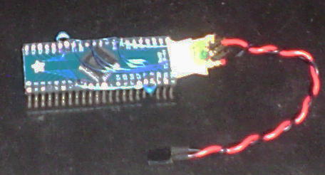
To prototype the device, I searched for useful boards, and NONE were using this particular CPU. However, at the time there was an
inexpensive generic TQFP44 breakout board
(OK it used to be available from Sparkfun, see left, but isn't any more) that worked PERFECTLY for building a simple prototype.
All I had to do was wire up the ISP header and a power supply, and provide some female headers for plugging wires into. I built two
different versions of these, and 'upgraded' the one you see here to include extra LEDs and an 'FTDI Friend' compatible pinout. In
any case, the end result of the original 2 prototypes was something that was a _little_ difficult to work with, but very effective for
prototyping the customer's hardware being driven by an ATXmega64D4 processor, and to allow a 3rd party to write custom software to do
firmware upgrades and data transfer, 2 months before the actual (assembled) boards arrived.
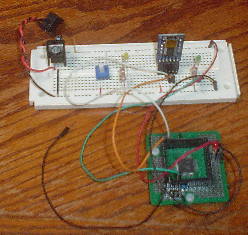
In the photo to the left, you can see one of the Sparkfun breakout boards with an ATXmega64D4 soldered on. There is also an ISP header
(bottom, left), and a set of female headers exposing ALL of the device's pins. The 4 Vcc and 4 ground pins are soldered together under
the board, and there are some 0.47µF filter capacitors across the power pins. Vcc is applied where the power LED is (at the right
side) and must be 3.3V regulated. The breadboard at the top has a 3.3v regulator (left), some LEDs, and an 'FTDI Friend' (available
from Adafruit) connected by jumper wires to one of the serial ports on the xmega. The default LED
output is connected to an LED and resistor (to ground) on the breadboard. Some additional components are also on the breadboard, which
had been used for testing, and aren't currently connected. The disconnected black wire (lower left) is connected to the reset pin on
the xmega.
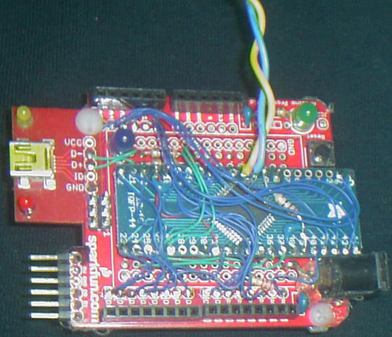
With a lack of TQFP-44 breakouts from Sparkfun, I checked elsewhere for something equivalent. I found something BETTER.
Adafruit now has a breakout board that works VERY well. In fact, they have a
LOT of breakout boards now (but unfortunately, no TQFP-100's). There is a photograph of a working prototype with an ATXMega64D4 on an
Adafruit breakout board at the top of this page. To the right of the device is a small LED + ISP/PDI header and the power supply cable
for 3.3VDC, taped on with white electrical tape. There are a handful of 'blue wires of salvation' on the board, basically wiring up the
power and a couple of bypass capacitors, plus wires to the LED+ISP/PDI board at the right. And what you get is something that's mostly
wired up for power and ISP programming that can be PLUGGED IN TO A BREADBOARD. In many ways it's like some of the breadboard-capable
Arduino clones out there [and they are VERY handy for testing things]. But you can somewhat easily make your own ATXMega64d4 version,
at a reasonably low cost, and that's the point.
Because the ATXmega series have a BUILT-IN 32Mhz clock (no external resonator or crystal required) there is no external oscillator nor
resonant circuits needed. This makes it VERY simple to create a near-Arduino-compatible device using a simple breakout board and some
extra wiring underneath the board to wire up the essential things (power, ground, filter caps, ISP header).
One important detail about the xmega series is that the old way of flashing a bootloader wasn't going to work. I was able to obtain
an AVRISP Mk II from a well-known electronics distributor, however, and this device works for both the ATMega and ATXmega devices.
Further, I am still able to use 'avrdude' (the open source AVR flash program, that Arduino also uses) to flash using the AVRISP Mk II,
under FreeBSD even. So no problems at all getting the hardware to accept an image, once I had updated the AVRISP Mk II firmware to
the latest version.
With that out of the way, it was just a matter of wiring up an ISP header (only 4 lines are used for the xmega, vs 6 for the ATMega
devices, so the 'middle 2' pins are unconnected) and programming the device.
One caveat remained: The boot section requires a special programming method. In short, you can't use the normal address offset for the code
section, since it will not write the boot section from there. Instead, you must specify the boot section. Even though the bootloader was
correctly assigned a start address of 10000H, the boot section's offset starts at 0000H, so you must program the first byte of the image
at 0000:0000H. To solve this problem, I did a simple text edit of the original 'hex' file, and created a modified 'hex' file in which the
initial address offset of 10000H is "left out", thus (effectively) specifying 0000:0000H. The bootloader flashed perfectly.
Initially I flashed code images using the AVRISP Mk II, until I was able to get serial programming working with the bootloader. Following
that, I was able to program applications using the Arduino environment itself, as if it were an Uno or other Arduino/compatible device.
Therefore, the net result of my efforts was to be able to write an Arduino script and program it onto an xmega-based device using the
Arduino IDE, just as I would any other Arduino/compatible device.
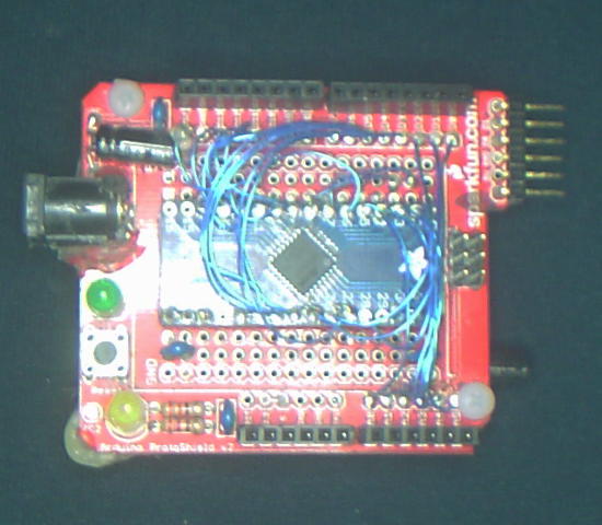
Building an actual Arduino Compatible Device
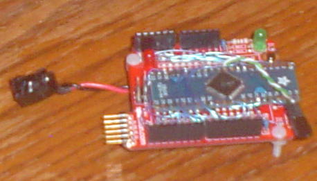
As an experiment, I actually built an Arduino-compatible device using the ATXMega64D4 processor. As you can see at the right of
the page, there's a board with Arduino-style pins and a 44-pin breakout board wired up to it, with an ATXMega64d4 on the breakout
board. The red board underneath is a blank shield board from Sparkfun. Since
I had no intent to actually use it as a 'shield' I just got the blank board, which is SO handy! The serial port pins
on the side were for Sparkfun's bluetooth serial adaptor. But I need to use it for the Adafruit FTDI cable (same pinout as FTDI
Friend) and so I had to 'hack' it a bit to make it work. So cut the power and ground pins, connect ground to one side, and hook a
capacitor and resistor for the reset line, and VOILA! Now, the serial flash process works PERFECTLY! And I also have the ISP header
already on the shield board on top of THAT. You couldn't ask for a better 'starting point' for setting up an Arduino clone board,
except maybe an actual Arduino board (minus the CPU connections).
Of course, this is a 3.3v board. The ATXMega64D4 doesn't work at 5V. But for compatibility with my OWN shields, I wired the 5V and
3.3V pins together. 5V was already wired up to the appropriate Arduino pin and broken out as a bus, and also on ISP and a couple of
other places. So wiring them together was the simplest way of making sure I power up with 3.3V, but have 3.3v available for shields on
the 3.3v line. Ok so it's not 100% compatible, but there you go. It demonstrates the concept and works with my TFT shield. That and I
didn't want to cut any traces. But it _IS_ something to be aware of if you make your OWN 'Arduino Compatible' with the Sparkfun shield board.
So with a bit of patience on the blue wires to each of the appropriate pins, I wired up the ATXMega64D4 processor to match the definition
in the 'pins_arduino.h' header file for the 'xmega64d4' variant. There's an ASCII art diagram for it. Wiring up wasn't too hard,
actually, and only took the better part of an afternoon to do it (with occasional profanity, of course, as I can't seem to solder
anything tedious without it).
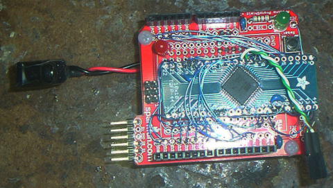
I tested this configuration with the ultimate test: a TFT 'shield' I created for an Arduino Uno. It has a color TFT device (that I
got from Adafruit, probably 2 years ago) that also has an SD card slot on it. I've tested with this firmware before, and so it was just
a matter of doing a build for the 'atxmega64d4' variant and VOILA! It works! Screen updates are twice as fast as the Arduino Uno
because the clock is at 32Mhz, and that affects SPI speed and the time it takes to refresh the TFT and read files from the SD card.
So in short EVERYTHING is twice as fast, and the SD card and TFT can both handle the higher clock speed.
FYI - the cable at the left is an Arduino-style power connector, and the cable at the right (with the 2 pins) is for the TWI pins.
Arduino Uno Rev 3 and mega2560 Rev 3 both break out separate TWI connections that aren't in the pinout for the earlier devices.
In this case I mapped the TWIC pins from PORTC, pins 0 and 1, to be unique TWI outputs on these 2 pins. Unfortunately the shield
board didn't have pins for these (it uses the old layout). So I broke them out on a separate connector so that it wouldn't interfere
with shields being plugged in, but I could still access them to experiment with TWI (I still need to work on it).
|
|
 The board on the far right is similar to the xmega64d4 prototype shown above, except that it has an ATXMega32E5 processor on it.
It has half of the NVRAM, and a bit less RAM and EEPROM, but comes in a TQFP32 package and costs considerably less than the
ATXmega64d4. Additionally, it has a dual channel D:A converter and some additional peripheral hardware.
The board on the far right is similar to the xmega64d4 prototype shown above, except that it has an ATXMega32E5 processor on it.
It has half of the NVRAM, and a bit less RAM and EEPROM, but comes in a TQFP32 package and costs considerably less than the
ATXmega64d4. Additionally, it has a dual channel D:A converter and some additional peripheral hardware.
 I have been told that the CPU model sufixes of '1' '4' and '5' refer to the number of pins and the case style; that is, the A1
series is an 'A' series CPU (for peripherals) that has 100 pins. The A4 series is an 'A" series CPU (for peripherals) that has
44 pins, a D4 series is a 'D' series CPU (for peripherals) with 44 pins, and the E5 series is an 'E' series CPU (for peripherals)
that has 32 pins. So an XMega64D4 has 64Kb of NVRAM, is a 'D' series, and has 44 pins.
I have been told that the CPU model sufixes of '1' '4' and '5' refer to the number of pins and the case style; that is, the A1
series is an 'A' series CPU (for peripherals) that has 100 pins. The A4 series is an 'A" series CPU (for peripherals) that has
44 pins, a D4 series is a 'D' series CPU (for peripherals) with 44 pins, and the E5 series is an 'E' series CPU (for peripherals)
that has 32 pins. So an XMega64D4 has 64Kb of NVRAM, is a 'D' series, and has 44 pins.
But in addition to the numeric suffix is the optional letter 'u', as in the case of the ATXMega128A4u, which is shown to the right
and below the ATXMega32E5 prototype board. The ATXMega128A4u is an 'A' series [which defines the built-in peripherals],
with 128Mb of NVRAM for code, a 44 pin package, and USB support. So the USB connector on the left of the photograph isn't just
there for show. This current prototype is still under development as I continue working on the USB support in the XMegaForArduino,
project, but I'm consider an actual board design.
|
|
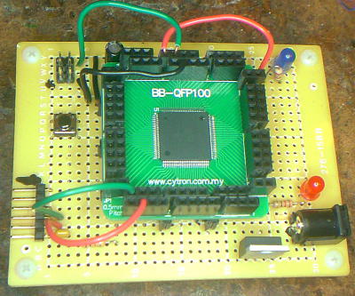 On a related note, the picture at the right is of an ATXMega128A1U ('u' being for USB support) on an inexpensive 100 pin QFP
breakout board,
which is then 'stilt mounted' onto a
Radio Shack proto board
that supplies power and has plugs for the serial port and ISP header.
Solid copper wires plug into the appropriate holes on the board. I'll need to add some ground and power busses (and a USB connector for
testing the USB capabilities of the ATXMega128A1U) but for NOW this tests that particular CPU pretty well. And yeah, it's got 100 pins.
The cpu really is a bit of a 'monster', with THAT many I/O pins, *AND* external RAM support, Yeah. Soldering the chip onto the breakout
board was tricky. I messed one of them up, had it rotated 90 degrees 'cause there are THREE marks, not just one, and you can't see them all
properly unless you shine the light on it 'just right', but if you get the text oriented right side up, the pin one mark is in the upper
left corner. The chips are kinda pricey, too, so you want to know what you're doing. But it IS possible with a standard soldering iron,
as long as you don't put too much solder onto the pads. Use a LOT of flux, a TEENY amount of solder 'on the iron', slide it back and forth
until all of the pins look good under a loupe. YES, under a loupe. Normal eyes can't see these things without magnification.
On a related note, the picture at the right is of an ATXMega128A1U ('u' being for USB support) on an inexpensive 100 pin QFP
breakout board,
which is then 'stilt mounted' onto a
Radio Shack proto board
that supplies power and has plugs for the serial port and ISP header.
Solid copper wires plug into the appropriate holes on the board. I'll need to add some ground and power busses (and a USB connector for
testing the USB capabilities of the ATXMega128A1U) but for NOW this tests that particular CPU pretty well. And yeah, it's got 100 pins.
The cpu really is a bit of a 'monster', with THAT many I/O pins, *AND* external RAM support, Yeah. Soldering the chip onto the breakout
board was tricky. I messed one of them up, had it rotated 90 degrees 'cause there are THREE marks, not just one, and you can't see them all
properly unless you shine the light on it 'just right', but if you get the text oriented right side up, the pin one mark is in the upper
left corner. The chips are kinda pricey, too, so you want to know what you're doing. But it IS possible with a standard soldering iron,
as long as you don't put too much solder onto the pads. Use a LOT of flux, a TEENY amount of solder 'on the iron', slide it back and forth
until all of the pins look good under a loupe. YES, under a loupe. Normal eyes can't see these things without magnification.
If done carefully, you can use good quality solder wick to remove excess solder that is causing pin-to-pin shorts, if you can't merely
'slide it away' using a soldering iron. And a flux pen is mandatory for successfully soldering those 'too small to see properly' pins.
Fortunately, flux pens are cheap, and so are loupes [digikey stocks plastic ones, I have 2 on hand], and if you work with modern
electronics, you really SHOULD own a loupe and a good lighted magnifier.
All of the power pins on the CPU are connected to 0.1" male breakout pins, that plug into corresponding female pins underneath. The female
breakout pins were individually cut and soldered onto the board. OK it was difficult doing it this way, but it make the board pluggable in
case I need to switch it out or fix something, and also exposes EVERY! SINGLE! NON! POWER! PIN! on the ATXMega128A1U. [so I'll need power
busses on the power supply 'support' board underneath, at some point].
I built this because I am currently adding support for additional ATMel 'xmega' CPUs, not just the ATXMega64D4, to the
XMegaForArduino project. The ATXMega128A1U is one of those.
|
Customizing the Arduino Environment for use with the XMega processors
The Arduino IDE does not natively support the xmega processors, although the build tools do. However, since the Arduino IDE
version 1.6, it is highly customizable using a well documented method. As such, the XMegaForArduino project has a setup file
that you can download with the Arduino IDE's "Package Manager". You should open the Arduino IDE, then select
'File' 'Preferences' [in Linux, using 1.8; your mileage may vary] and then the 'Network' tab to access the Package Manager.
Then,
install this file using the Arduino IDE's Package Manager Manager. Additional Documentation on the Arduion IDE's
Package Manager and environment can be found on the 'arduino.cc' web site, and is somewhat beyond the scope of this web site.
OLD METHOD: Customizing the Arduino Environment
If you are using a version of the Arduino IDE newer than 1.6, you do not need to read this section. Otherwise, if all
you have is an older Arduino IDE, such as from a Linux distribution that has not updated to the newer IDE, you may still
need to do this.
Some time ago I submitted a short article to the Arduino Playground
wiki site regarding customization of the Arduino IDE for different kinds of hardware. In short, I described what I had done so far
with respect to the ATXmega64D4 processor and the customer's device. There are several specific modifications that need to be made,
all of which are necessary to make the Arduino IDE work with a new type of processor.
Although there is already a GitHub project for an 'xmega' version of the Arduino IDE, I did not see the need to modify the entire thing
just to handle a new CPU. In fact, it seems so easy to modify the existing Arduino IDE with a simple patch, that the need for modifying
the entire environment was just too impractical. It also makes it VERY easy to update to a new version of the IDE. I based my modifications
on Arduino 1.05 since that's what I had installed under FreeBSD.
The sub-directories I list here exist within the Arduino IDE directory tree. Typically this will be /usr/local/arduino (as on FreeBSD),
or /usr/share/arduino (as on Ubuntu 12.04). On windows or OSX, your mileage may vary.
The 'boards.txt' file
The 'boards.txt' file resides in the Arduino IDE's 'hardware/arduino' sub-directory, and contains entries that describe the various
board types, and the correct sub-directories and compiler CPU settings to use when compiling for that particular board. Using the supplied
patch file (or manually editing boards.txt) allows you to specify a new board type for an ATXmega64D4 device. An appropriate entry would
describe the 'cores' and 'variants' sub-directory as well as the flash method and CPU for your particular hardware. If you examine the
'boards.txt' file, you will find a number of different Arduino and compatible devices listed. When you look in the appropriate 'cores'
or 'variants' sub-directory, you'll see CPU-specific and board-specific implementations of the Arduino API functions and definition files.
Setting these correctly in 'boards.txt' allows you to customize the Arduino IDE to work with whatever board configuration you might have,
so long as it is possible to map everything properly.
The 'cores' sub-directory
Within the 'cores' sub-directory are a number of CPU-specific sub-directories, each named according to the type of
device. The main directory is 'arduino', and corresponds to the ATmega328p (and related) CPUs for Arduino and compatibles.
The corresponding entry in the 'boards.txt' file will be 'xxx.build.core', where 'xxx' is the name for your boards.txt
entries, and the entry value will be the sub-directory name (such as 'arduino'). The source and header files within this sub-directory
implement the startup code (device initialization), the timer functions, the serial port, and both the analog and
digital I/O, as well as a few other features (like the 'Tone' library). In short, it's a hardware abstraction for the type of
CPU you are using, but is generally NOT board-specific.
On non-windows systems, it is possible to use a symbolic link to point to a directory containing your own implementation. This
is recommended for OSX, Linux and BSD installations, so that you do not have to modify the actual Arduino directory structure.
The 'variants' sub-directory
Within the 'variants' sub-directory are a number of board-specific directories, each definining the pin-to-pin mapping for the
various analog and digital I/O pins. In short, it implements the board-specific 'abstraction' header file 'pins_arduino.h'. For
the 'xmega' implementation, D2 is mapped to digital pin 0, D3 to pin 1, and so forth, so that the serial port on port D will map
to the same pins as the serial port on an ATmega328p.
On non-windows systems, it is possible to use a symbolic link to point to a directory containing your own implementation. This
is recommended for OSX, Linux and BSD installations, so that you do not have to modify the actual Arduino directory structure.
The 'avrdude.conf' file
An additional file, one that is used by 'avrdude', is the 'avrdude.conf' file. It contains information that avrdude needs in order
to flash a device. You can modify this file using the supplied patch file in the Arduino IDE patch tarball for the ATXmega64D4. Other
ATXmega series processors should already implemented, though. It seems that only the D4 was missing, but as it is not supported by
the existing avr compilers (without the patches I made), it is understandable.
The 'avrdude.conf' file is located in various places, depending upon your implementation. On FreeBSD, it is in /usr/local/etc/avrdude.conf .
On Ubuntu 12.04, it is /etc/avrdude.conf . A symbolic link to this file is typically in the hardware/tools directory within the Arduino
environment.
The 'sketchbook' sub-directory (in the user's 'Home' directory)
When you set up the Arduino IDE, you can specify a default sub-directory for your sketches. Typically this will
be the 'sketchbook' directory within the user's Home directory. If you create a sub-directory 'libraries' within
this sketchbook directory, and populate it with library sub-directories, the Arduino environment will search for
libraries HERE, in addition to the default libraries in the Arduino IDE's directory tree. As such, if you need to
customize a library (let's say the SD card library) to work with the xmega, you would need to make a copy of it into
your own library tree, and modify the code accordingly. This also makes it possible to have customized library versions
of just about any Arduino library, ones that contain fixes or implement specific functions that YOUR projects need. So
if you do not want to modify the existing Arduino libraries to work with the xmega
|
My 'xmega' Implementation - The XMegaForArduino project
In support of the xmega processors (in general), and because of a customer project that needed it, I created
the XMegaForArduino project, which is officially located on github.
Prior to a somewhat recent gcc version (4.8.3), there was no support for the atxmega64d4 for 'avr-gcc' (and related tools).
As a result, I produced my own modifications for the compiler suite (which I then submitted to appropriate places). All of
the necessary patches are available on the XMegaForArduino project in the 'patches' directory.
Here is a short list of features:
- Startup code correctly sets up the internal 32Mhz clock
- Support for both 'arduino' and 'wiring' flash protocol (USB bootloader in the works)
- Compatible timers and time-related functions
- Some additional xmega-specific features, like 'wait for interrupt' and advanced IO pin capabilities
- Dual serial ports. The 'Serial' object uses port D, for easy mapping to digital pins 0 and 1.
- Compatible Digital I/O as well as additional support for the xmega's more advanced pull up/down
and open drain/source configurations, using bit flags
- Support for asynchronous interrupts on pin '2' of each port, and synchronous interrupts on any other port's pin.
- Additional support for xmega's advanced interrupt trigger types (high or low level, low-to-high, high-to-low, change).
- Compatibility mode for analogRead, configured to behave as the ATmega328 would behave (10-bit value, 0 to Vcc).
- Can generate PWM via analogWrite on nearly all of the digital I/O pins (on most xmega CPUs).
Here is a short list of items to be completed:
- Tone library (part of the 'cores' source)
- Two Wire implementation for xmega (using TWIC; TWIE does not appear to work properly at this time)
- Ethernet and other standard library support (as needed)
Related ATXmega Projects and Breakout Boards
- Akafuino X XMega32A4 Microcontroller Board
- Xaduino Xmega128A3U Xmega Based Arduino System
- 0603.eu ATXmega32E5 breakout board v2
- Sparkfun ATXmega128A1 breakout board
- MCU ZoneATxmega128A1U mini board (via Ali Express)
- Adafruit TQFP44 breakout board
- MC Pros Universal QFP breakout board (32-100 pins, 10-pack)
This board should work with a LOT of different CPU case types, particularly a QFP-100. This one is 0.5mm pitch (others also available)
- Robot Shop Cytron QFP breakout board (others also available), not as easy to solder as the one above, but much less expensive
- Proto Advantage QFP-100 to 100 pin DIP breakout board (others also available HERE)
With THIS you should be able to use a regular breadboard on all 100 pins. It's a little pricey but may be well worth it, depending on your project
- Xmegaduino Development Environment: Github Page
- Wikipedia Page on QFP packaging
Notes on Debian and Ubuntu 'source' packages
In the 'Source Download' section, below, there are some OLD packages for Ubuntu 12.04 and Debian 'Wheezy' that were
pre-built for specific architectures. If your architecture is different, you can build from source using
a procedure similar to the following:
- Download the appropriate package tarball and extract the tarball contents into an appropriate directory
- For each of the 3 packages, do '[sudo] apt-get build-dep {packagename}' where 'packagename' is 'avr-libc', 'binutils-avr', and 'gcc-avr'
- Use 'dpkg-source' to extract the '.dsc' similar to the following:
dpkg-source -x avr-libc_1.8.0-2.1.dsc
- change directory to the package source directory (in this case avr-libc_1.8.0-2.1) and do the following:
fakeroot debian/rules binary
This will build the package as a '.deb' in the same directory you extracted the tarball into.
- once the packages are built, you can install the package as follows:
[sudo] dpkg -i avr-libc_1.8.0-2.1_[your architecture].deb
The build+install order is avr-libc, binutils-avr, and then gcc-avr.
NOTE: since avr-libc is an 'all' package, you probably won't need to build this one, and can install the 'all' version as-is.
But if you want to re-build it anyway, you still can.
|