Emulating Hardware Through Software
One thing that is common in the world of consumer electronics is the need to perform some kind of custom logic feature, from button user interfaces to LCD displays and flashing lights. If manufacturers needed to create their own custom logic chips to perform these functions, consumer electronics would be prohibitively expensive. So for DECADES microcontrollers have been used inside common devices to perform the necessary operation in response to button clicks and remote control codes, GREATLY reducing the cost, and the price to the end user.
Aside from the OBVIOUS uses, it is ALSO possible to use existing inexpensive microcontrollers to substitute for a large number of electronic components (or a custom-developed chip). And in certain cases, it may even be LESS EXPENSIVE (in the long run) to use a microcontroller in the design to substitute for EXISTING devices.
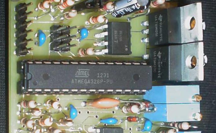
Let's take the example of the S.F.T. Power Supply, a prototype device that uses a microcontroller to regulate 4 separate voltages at the same time. Sure, switching power supplies aren't new, nor is using PWM to control an output voltage, or an A:D converter to measure a voltage. PWM and A:D converters are built-in features in the AVR processors made by Atmel. Taking advantage of them in NEW ways, however, is part of the power of the microcontroller. That is, USING SOFTWARE TO REPLACE HARDWARE.
The S.F.T. Power Supply still need a number of external components to do its job. Most of these are discrete components like power transistors, diodes, resistors, capacitors, and filter chokes. These would be required ANYWAY if a dedicated switching power supply control chip were used, such as one of those produced by Linear Technology, you would STILL need to surround the somewhat-expensive controller device with a number of standard off-the-shelf discrete components for it to work. By using a microcontroller, with appropriate software, to do what a switching power supply controller does, the number of components on the board probably won't change much. HOWEVER, the total cost of the unit is likely to be LOWER than it was before. By my comparison, a typical AVR processor costs LESS THAN HALF of the cost of a typical switching power supply device. You, the reader, are invited to do similar comparisons.
And THIS was the primary reason for developing the S.F.T. Power Supply prototype: to prove that a software algorithm COULD be used on an AVR processor to regulate voltages. In fact, one AVR processor is regulating 4 voltages, and not just one. So instead of having to use 4 control chips (now 8 times the cost of a single AVR CPU) I only need 1. I think the cost savings alone should demonstrate why THIS has the potential of saving a great deal on the B.O.M. costs for a device
Of course, this means writing control software, which can take quite a bit of time. But if it gives you a competitive advantage, it's definitely worth it. A lot of engineering work is devoted to saving PENNIES on the B.O.M. cost, and if you have to spend THAT kind of money engineering a few cents, think of what it would be worth to save SEVERAL DOLLARS. When manufacturing in large quantities, the 'fixed cost' of the software engineering essentially becomes NEGLIGIBLE with respect to the per-unit B.O.M. costs, and the reduction in retail sales price (or improved margin) will reflect the pennies or single dollar savings per unit. It is why it's worth spending many tens of thousands of dollars on this kind of engineering work.
Using the S.F.T. Power Supply as a model, a microcontroller is typically a RUN TIME device that polls measurements and makes adjustments to control whatever devices it's designed to control. In some cases it makes more sense to use interrupts and ISRs, but those would more likely be specialized applications and NOT the 'general use'. Since AVR processors CAN do ISRs (and I do make use of an ISR in the S.F.T. Synth project) they are still an option for when such a thing is needed.
The Main Loop of a microcontroller typically runs indefinitely so long as power is applied. Each step
in the loop is performed sequentially, and care must be taken that no one step takes more time than can be
afforded so that response to changes in the controlled system are not hampered. The main loop for the S.F.T.
Power Supply is called repeatedly by the startup code, so long as the device has power. It looks something like this:
  void loop()
  {
  short i1, s1;


    serial_check(); // periodically check serial input for whatever

    sGlobalActualBias = MyAnalogRead(ACTUAL_BIAS); // read once per loop (assume it won't change, much)

    // re-calculate the moving averages for the current data (global vars)
    sPosUP = (sPosUP * 2 + MyAnalogRead(POS_UNREG_UP)+DoBiasAdjust()) / 3;
    sPosDN = (sPosDN * 2 + MyAnalogRead(POS_UNREG_DN)+DoBiasAdjust()) / 3;
    sNegDN = (sNegDN * 2 + MyAnalogRead(NEG_UNREG_DN)+DoBiasAdjust()) / 3;
    sNegUP = (sNegUP * 2 + MyAnalogRead(NEG_UNREG_UP)+DoBiasAdjust()) / 3;

    if(bCalibrate)
    {
      cal_loop();
      bSnapVerbose = 0;
      return;
    }

    if(bOverload)
    {
      MyAnalogWrite(HV_REG_PIN, 0);  // pin 3
      MyAnalogWrite(INT_40V_PIN, 0); // pin 5
      MyAnalogWrite(INT_NEG_PIN, 0); // pin 6
      MyAnalogWrite(POS_REG_PIN, 0); // pin 9  - NOTE:  shutting off PWM must cause 0V output
      MyAnalogWrite(NEG_REG_PIN, 0); // pin 10 -        same here (make it a mirror of positive PWM)
      MyAnalogWrite(HV_BIAS_PIN, 0); // pin 11

      MyLCDClear();
      MyLCDOut_P(PSTR("  **OVERLOAD**  "));
      MyLCDLine2();
      MyLCDOut_P(PSTR("  ============  "));

      // auto-reset (for now)
      delay(9000); // wait 9 seconds

      MyLCDLine2();
      MyLCDOut_P(PSTR("AUTO-CLEARED!"));
      delay(1000);
      MyLCDClear();
      bOverload = 0;
      bSnapVerbose = 0;

      return;
    }

    if(bUncalibrated)
    {
      // uncalibrated means I need to do a special loop for the HV
      do_special_hv_reg_loop(); // same as when I'm calibrating, which reflects I'm uncalibrated

      s1 = (short)((long)get_check_setting(0) * 220L / 1023L);
      // this will be the estimated PWM output for the +/- LV PWM outputs
      // it is needed to perform the calibration, and also verify the unit is functioning

      if(s1 < 0)
      {
        s1 = 0;
      }
      else if(s1 > 220)
      {
        s1 = 220;
      }

      MyAnalogWrite(POS_REG_PIN, 240 - s1);
      MyAnalogWrite(NEG_REG_PIN, 20 + s1);

      for(i1=1; i1 < NUM_CALDATA_CHANNEL; i1++)
      {
        get_check_setting(i1); // do this for now to prevent trouble
      }
    }
    else
    {
      // loop through each regulated channel and adjust the PWM output

      for(i1=0; i1 < NUM_CALDATA_CHANNEL; i1++)
      {
        sGlobalActualBias = MyAnalogRead(ACTUAL_BIAS); // read once per loop (assume it won't change, much)
        adjust_pwm(i1, get_check_setting(i1));
      }
    }

    DoLCDUpdates(); // update the display with live voltage measurements, etc.

    // TODO:  anything else per loop?
  }
One important thing to consider about microcontrollers is that they are GENERAL PURPOSE devices, and may not have the kinds of response time or features necessary to provide proper control. Sometimes it is possible to engineer around this, sometimes not. In the case of the S.F.T. Power Supply, larger capacitors and inductors are necessary to accomodate the relatively slow switching speeds of the PWM output (typically, 8khz). Even though it is possible to control 4 outputs, there are delays that MIGHT allow a transient voltage to exceed the specifications of the downstream components. Ideally the components MUST filter out such transients, or some other external circuit (such as a crowbar) must be employed to prevent this from happening. Transient response is an important design criteria since a voltage DIP (which might reset a CPU) is just as bad as a voltage SURGE (which might fry power-sensitive devices). So using a microcontroller in POWER SENSITIVE situations might not be the best idea. However, if the microcontroller were to control the MAIN voltages, and a specialized regulator controls the POWER SENSITIVE voltages, you can end up with a hybrid solution that takes advantage of "The Best of Both Worlds".
So a microcontroller-based solution is NOT a panacea "one-size-fits-all" solution. But careful design of a microcontroller-based solution CAN reduce the cost of a device, and maybe even give it other capabilities that were not previously possible.
©2013 by Stewart~Frazier Tools, Inc. - all rights reserved
Last Update: 7/18/2013